HW Domnit Alexandru
Requirements
Implement given project in Packet Tracer.
Screenshots from each computer in the network to prove functionality.
Given initial data

Doc
Packet Tracer tutorial.
Understanding Address spaces and subnetting in IPv4.
ProiectComplet YT
Solution
Computations for network IP`s
Main Network IP:69.122.240.0/24
Subnet Mask:255.255.255.0
Total available IP`s: 2^8=256 (from /24 submask)
Given Sub-Network requirements:
- N1: 56 IP’s
- N2: 24 IP’s
- N3: 12 IP’s
- N4: 20 IP’s
- N5: 4 IP’s
Identify all the present networks
Therefore we can find nontrivial networks as:
N5w: 2 ip`s
N12: 2 ip`s
N23: 2 ip`s
N34: 2 ip`s
N45: 2 ip`s
Computations for each subnet
For each subnet we add:
1 for Network Address (NA)
1 for Broadcast Address (BA)
Formula: Total required IP`s = Hosts + 1(NA) + 1(BA)
N1: 56 hosts
N1: 59 ip < 64 = 2^6 => 32-6 = 26 <=> /26
N2: 24 hosts
N2: 27 ip < 32 = 2^5 => 32-5 = 27 <=> /27
N3: 12 hosts
N3: 15 ip < 16 = 2^4 => 32-4 = 28 <=> /28
N4: 20 hosts
N4: 23 ip < 32 = 2^5 => 32-5 = 27 <=> /27
N5: 4 hosts
N5: 7 ip < 8 = 2^3 => 32-3 = 29 <=> /29
The other networks
N5w: 4 ip /30
N12: 4 ip /30
N23: 4 ip /30
N34: 4 ip /30
N45: 4 ip /30
Boildown of the computations:
| Subnet | Hosts | Required IP`s | Allocated IP`s | Subnet Mask |
|---|---|---|---|---|
| N1 | 56 | 59 | 64 | /26 |
| N2 | 24 | 27 | 32 | /27 |
| N3 | 12 | 15 | 16 | /28 |
| N4 | 20 | 23 | 32 | /27 |
| N5 | 4 | 7 | 8 | /29 |
Total allotted IP`s : 64+32+16+32+8+5*4=172
Since 172<256 this allocation fits.
Binary Tree
/24 256
/25 128
/26 64
/27 32
/28 16
/29 8
/30 4
N1=64 + N2=32 + N4=32 + N3=16 + N5=8 + 4 + 4 + 4 + 4 + 4
Now we can recursively split the range into appropriate chunks:
[0..63][64..95][96..127][128..143][144..151][152..155][156..159][160..163][164..167][168..171]
IP plan
| Subnet | Range | Subnet Mask | Usage |
|---|---|---|---|
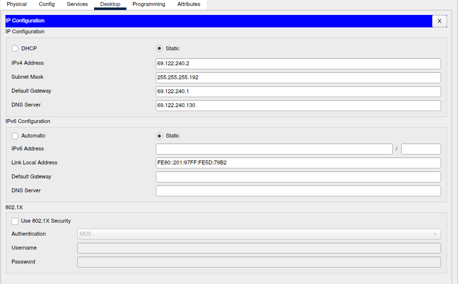
| N1 | 69.122.240.0 - 69.122.240.63 | /26 | R1=.1 S1DHCP=.2 |
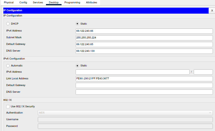
| N2 | 69.122.240.64 - 69.122.240.95 | /27 | R2=.65 S2WEB=.66 |
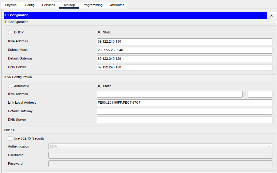
| N3 | 69.122.240.128 - 69.122.240.144 | /28 | R3=.129 S3DNS=.130 |
| N4 | 69.122.240.96 - 69.122.240.127 | /27 | R4=.97 |
| N5 | 69.122.240.144 - 69.122.240.151 | /29 | R5=.145 |
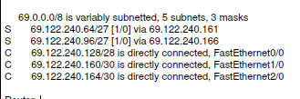
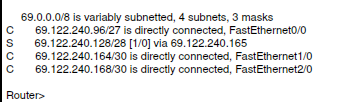
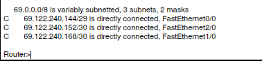
| N5W | 69.122.240.152 - 69.122.240.155 | /30 | R5=.153 RW=.154 |
| N12 | 69.122.240.156 - 69.122.240.159 | /30 | R1=.157 R2=.158 |
| N23 | 69.122.240.160 - 69.122.240.163 | /30 | R2=.161 R3=.162 |
| N34 | 69.122.240.164 - 69.122.240.167 | /30 | R3=.165 R4=.166 |
| N45 | 69.122.240.168 - 69.122.240.171 | /30 | R4=.169 R5=.170 |
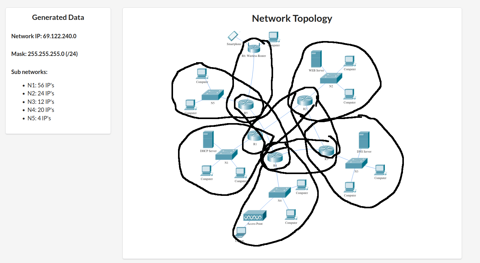
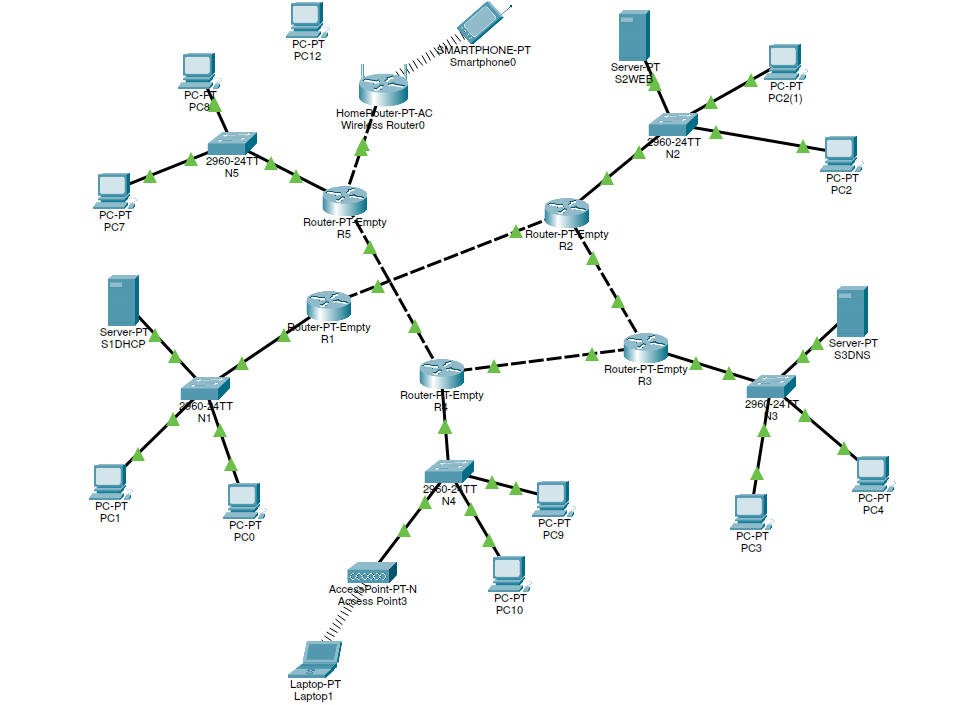
Implementation
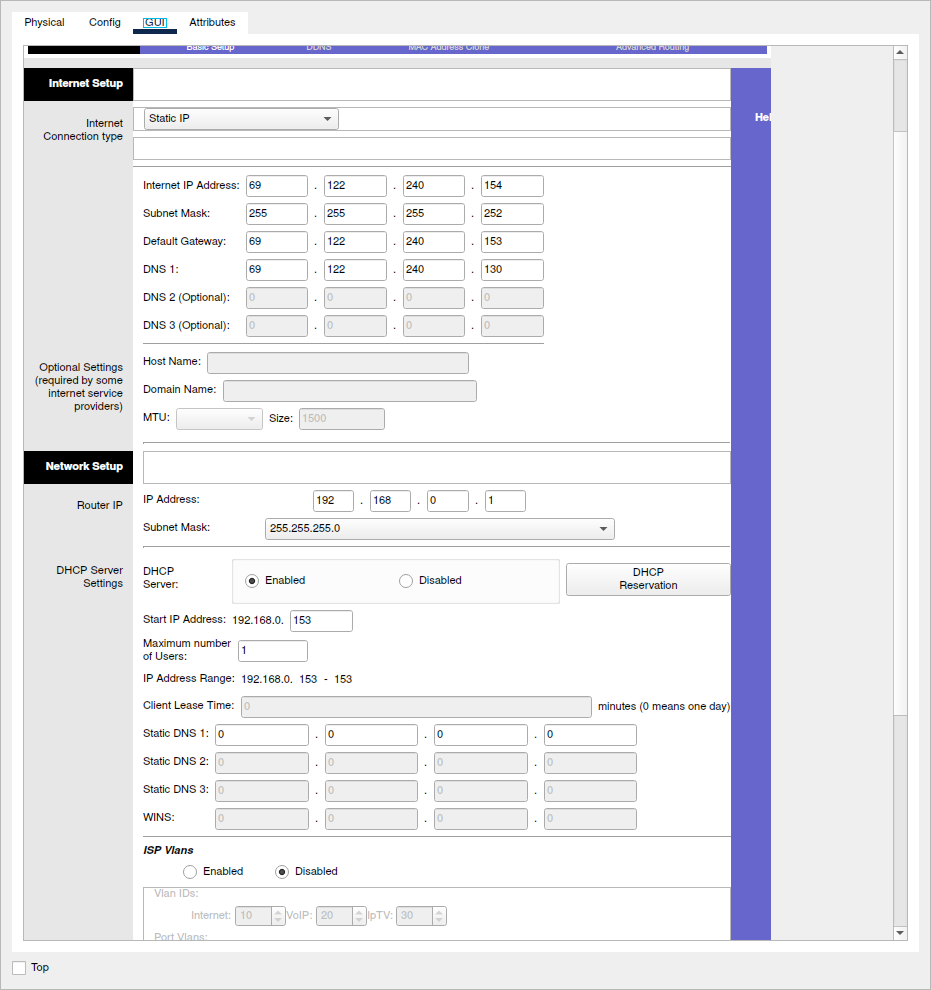
I`ve implemented the reuqired network plan into PacketTracer by firstly creating each subnet and then linking them all together. All the router and server settings are done according to the enumeration above.
Photos of the setup
Router 1:
Router 2:
Router 3:
Router 4:
Router 5:
Router 5 wireless:
Server 1 DHCP:
Server 2 WEB:
Server 3 DNS:
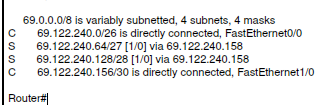
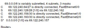
Pinging web server from different subnets
The web server is in N2 and it sits at ip: 69.122.240.66
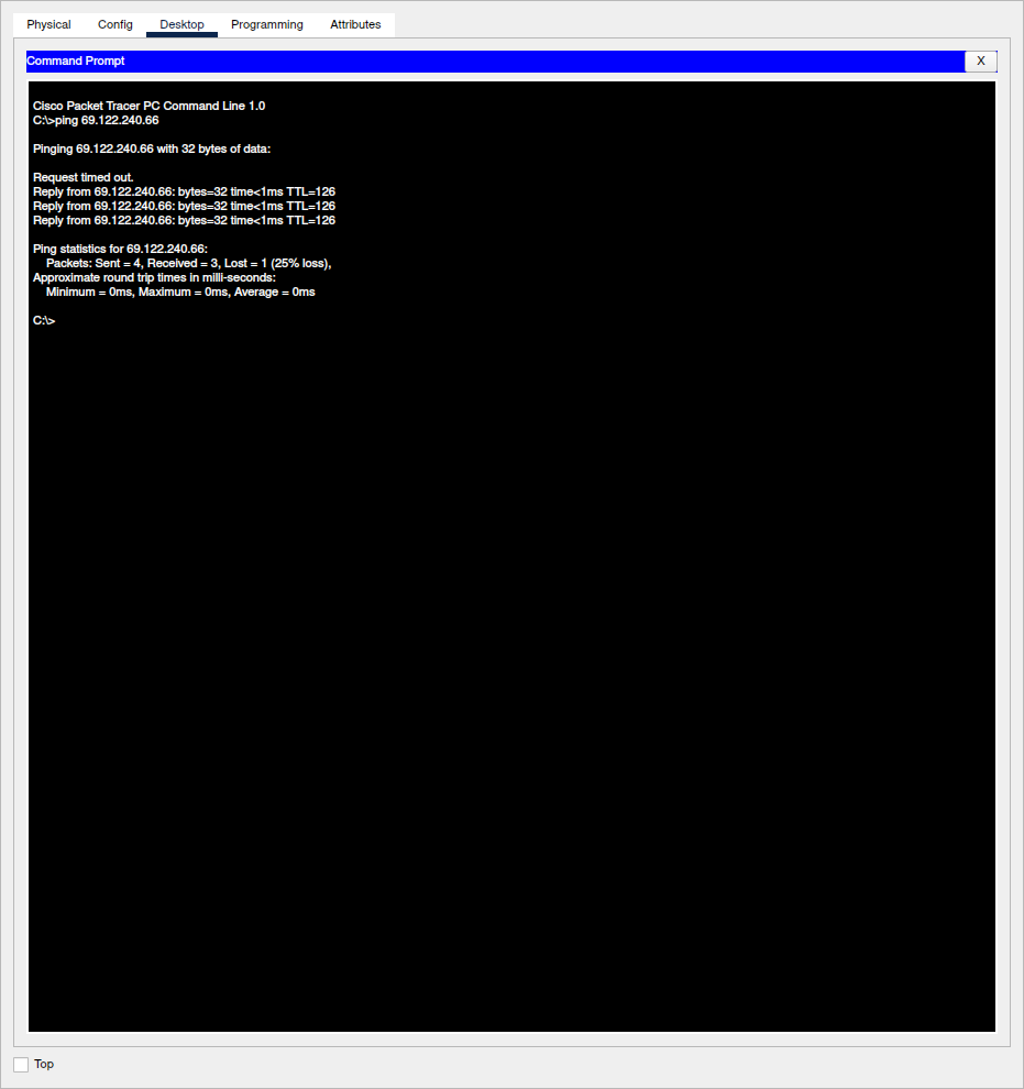
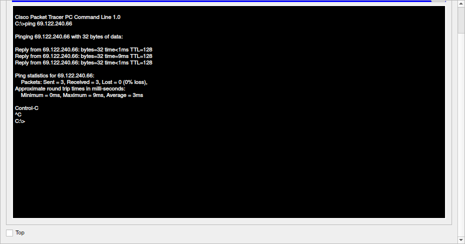
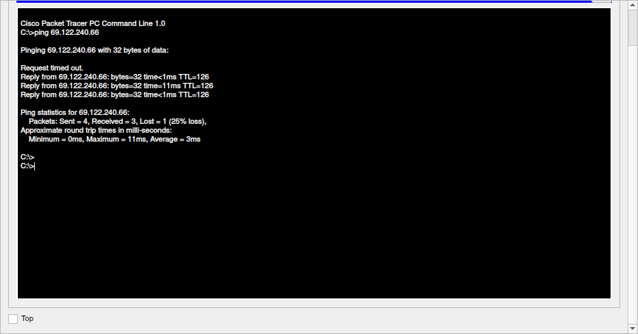
I statically routed the routers in the network, R4 routing doesn`t work, dk why.
The ip calcs and PT source file can be found at PT.